At present, China’s photovoltaic power generation system is mainly a DC system, which is to charge the electric energy generated by the solar battery, and the battery directly supplies power to the load. For example, the solar household lighting system in Northwest China and the microwave station power supply system far away from the grid are all DC system. This type of system has a simple structure and low cost. However, due to the different load DC voltages (such as 12V, 24V, 48V, etc.), it is difficult to achieve standardization and compatibility of the system, especially for civilian power, as most of the AC loads are used with DC power. It is difficult for the photovoltaic power supply to supply electricity to enter the market as a commodity. In addition, photovoltaic power generation will eventually achieve grid-connected operation, which must adopt a mature market model. In the future, AC photovoltaic power generation systems will become the mainstream of photovoltaic power generation.
The requirements of photovoltaic power generation system for inverter power supply
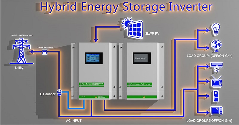
The photovoltaic power generation system using AC power output consists of four parts: photovoltaic array, charge and discharge controller, battery and inverter (the grid-connected power generation system can generally save the battery), and the inverter is the key component. Photovoltaic has higher requirements for inverters:
1. High efficiency is required. Due to the high price of solar cells at present, in order to maximize the use of solar cells and improve system efficiency, it is necessary to try to improve the efficiency of the inverter.
2. High reliability is required. At present, photovoltaic power generation systems are mainly used in remote areas, and many power stations are unattended and maintained. This requires the inverter to have a reasonable circuit structure, strict component selection, and require the inverter to have various protection functions, such as input DC Polarity connection protection, AC output short circuit protection, overheating, overload protection, etc.
3. The DC input voltage is required to have a wide range of adaptation. Since the terminal voltage of the battery changes with the load and the intensity of sunlight, although the battery has an important effect on the battery voltage, the battery voltage fluctuates with the change of the battery’s remaining capacity and internal resistance. Especially when the battery is aging, its terminal voltage varies widely. For example, the terminal voltage of a 12 V battery can vary from 10 V to 16 V. This requires the inverter to operate at a larger DC Ensure normal operation within the input voltage range and ensure the stability of the AC output voltage.
4. In medium and large-capacity photovoltaic power generation systems, the output of the inverter power supply should be a sine wave with less distortion. This is because in medium and large-capacity systems, if square wave power is used, the output will contain more harmonic components, and higher harmonics will generate additional losses. Many photovoltaic power generation systems are loaded with communication or instrumentation equipment. The equipment has higher requirements on the quality of the power grid. When the medium and large-capacity photovoltaic power generation systems are connected to the grid, in order to avoid power pollution with the public grid, the inverter is also required to output a sine wave current.
The inverter converts direct current into alternating current. If the direct current voltage is low, it is boosted by an alternating current transformer to obtain a standard alternating current voltage and frequency. For large-capacity inverters, due to the high DC bus voltage, the AC output generally does not need a transformer to boost the voltage to 220V. In the medium and small-capacity inverters, the DC voltage is relatively low, such as 12V, For 24V, a boost circuit must be designed. Medium and small-capacity inverters generally include push-pull inverter circuits, full-bridge inverter circuits and high-frequency boost inverter circuits. Push-pull circuits connect the neutral plug of the boost transformer to the positive power supply, and two power tubes Alternate work, output AC power, because the power transistors are connected to the common ground, the drive and control circuits are simple, and because the transformer has a certain leakage inductance, it can limit the short-circuit current, thus improving the reliability of the circuit. The disadvantage is that the transformer utilization is low and the ability to drive inductive loads is poor.
The full-bridge inverter circuit overcomes the shortcomings of the push-pull circuit. The power transistor adjusts the output pulse width, and the effective value of the output AC voltage changes accordingly. Because the circuit has a freewheeling loop, even for inductive loads, the output voltage waveform will not be distorted. The disadvantage of this circuit is that the power transistors of the upper and lower arms do not share the ground, so a dedicated drive circuit or an isolated power supply must be used. In addition, in order to prevent the common conduction of the upper and lower bridge arms, a circuit must be designed to be turned off and then turned on, that is, a dead time must be set, and the circuit structure is more complicated.
The output of push-pull circuit and full-bridge circuit must add a step-up transformer. Because the step-up transformer is large in size, low in efficiency, and more expensive, with the development of power electronics and microelectronics technology, high-frequency step-up conversion technology is used to achieve reverse It can realize high power density inverter. The front-stage boost circuit of this inverter circuit adopts push-pull structure, but the working frequency is above 20KHz. The boost transformer adopts high-frequency magnetic core material, so it is small in size and light in weight. After high-frequency inversion, it is converted into high-frequency alternating current through a high-frequency transformer, and then high-voltage direct current (generally above 300V) is obtained through a high-frequency rectifier filter circuit, and then inverted through a power frequency inverter circuit.
With this circuit structure, the power of the inverter is greatly improved, the no-load loss of the inverter is correspondingly reduced, and the efficiency is improved. The disadvantage of the circuit is that the circuit is complicated and the reliability is lower than the above two circuits.
Control circuit of inverter circuit
The main circuits of the above-mentioned inverters all need to be realized by a control circuit. Generally, there are two control methods: square wave and positive and weak wave. The inverter power supply circuit with square wave output is simple, low in cost, but low in efficiency and large in harmonic components. . Sine wave output is the development trend of inverters. With the development of microelectronics technology, microprocessors with PWM functions have also come out. Therefore, the inverter technology for sine wave output has matured.
1. Inverters with square wave output currently mostly use pulse-width modulation integrated circuits, such as SG 3 525, TL 494 and so on. Practice has proved that the use of SG3525 integrated circuits and the use of power FETs as switching power components can achieve relatively high performance and price inverters. Because SG3525 has the ability to directly drive power FETs Capability and has internal reference source and operational amplifier and undervoltage protection function, so its peripheral circuit is very simple.
2. The inverter control integrated circuit with sine wave output, the control circuit of the inverter with sine wave output can be controlled by a microprocessor, such as 80 C 196 MC produced by INTEL Corporation, and produced by Motorola Company. MP 16 and PI C 16 C 73 produced by MI-CRO CHIP Company, etc. These single-chip computers have multiple PWM generators, and can set the upper and upper bridge arms. During the dead time, use the INTEL company’s 80 C 196 MC to realize the sine wave output circuit, 80 C 196 MC to complete the sine wave signal generation, and detect the AC output voltage to achieve Voltage stabilization.
Selection of Power Devices in the Main Circuit of the Inverter
The choice of the main power components of the inverter is very important. Currently, the most used power components include Darlington power transistors (BJT), power field effect transistors (MOS-F ET), insulated gate transistors (IGB). T) and turn-off thyristor (GTO), etc., the most used devices in small-capacity low-voltage systems are MOS FET, because MOS FET has lower on-state voltage drop and higher The switching frequency of IG BT is generally used in high-voltage and large-capacity systems. This is because the on-state resistance of MOS FET increases with the increase of voltage, and IG BT is in Medium-capacity systems occupies a greater advantage, while in super-large-capacity (above 100 kVA) systems, GTOs are generally used as power components.
Post time: Oct-21-2021